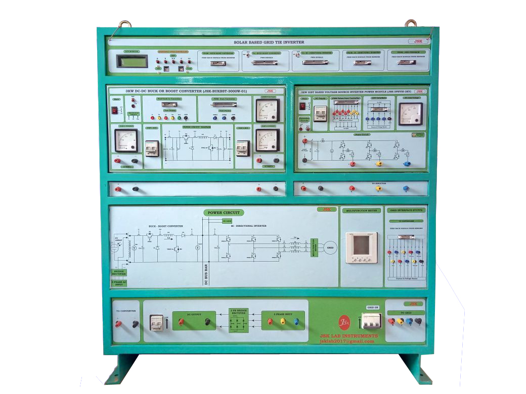
2.5KW GRID-TIED INVERTER:
- 3KW DC-DC BUCK OR BOOST CONVERTER———–1 No
- 3KW IGBT Based 3PH VOLTAGE SOURCE INVERTER—–1 No
- FPGA SPARTAN6 BASED CONTROLLER—–1 No
- GRID SIDE INTERFACE STUFF
- 3ph,1kw VARIABLE FREQUENCY DRIVE—-1 No
DC-Dc Buck or Boost Converter
- 2Nos of Switching device SEMIKRON IGBT Rating @1200v,100A,20khz with proper heatsink and snubber circuit Used to form power circuit.
- Input voltage range
- Minimum: 300v Dc
- Output voltage range
- Maximum: 600V Dc
- Output power : 3000W(max)
- Switching Frequency—5-20khz
- 2 Nos of HCPL316J IC-based PWM driver circuit used
- One Hall effect current sensor used to sense Input current
- One Hall effect current sensor is used to sense Inductor current and overload trip purpose.
- One hall effect voltage sensor is used to sense the I/P voltage.
- One hall effect voltage sensor is used to sense the o/p voltage.
- Voltage and current sensor o/pts terminated in front panel bs2 connector.
- Overload fuse protection is available.
- One no of 4inch cooling fan used to dissipate switching device heat
GRID SIDE INTERFACE STUFF:
- LA25-P HALLEFFECT Current sensors with signal conditioner – 3 Nos (25Amps Current sensor), which is used to measure the grid side current.
- Three Nos of hall effect voltage sensors (LV20-P) with signal conditioners are used to sense the grid voltage.
- 3Nos of Inductor Used to filter the grid side injected current.
- 4.3ph OP-AMP-based ZCD circuit used to generate synchronized PWM signals.
For More details contact: 7667134364

2.3KW IGBT Based 3PH VOLTAGE SOURCE INVERTER:
- Input: 1 Phase /3 phase 50 Hz AC.
- Output: 400V/10A (MAX), AC/DC on each Leg of 3 phase Bridge
- 3Nos 1200V, 100A SEMIKRON IGBT MODULE Used to form Inverter Bridge.Each IGBT module consists of two IGBTs.
- Built-in Short circuit, over current & over Temperature Protection available.
- 1200V, 60A Converter Bridge for AC-DC power conversion
- 15v/2A SMPS power supply and converter used to generate 4nos of isolated +15v supply for gate driver section.
- 4 Nos of Hall Effect current sensors(LEM MAKE-LA25-P) to sense the DC Link current & 3 output Currents of the Inverter Bridge.
- 6 nos of HCPL316J ic-based negative turn-off driver circuit will be used.
- All the PWM signals are isolated using Upto Isolator
- Protection circuit for over current with LED indication
- Optically Isolated Fault signal from the driver is given to the Embedded/DSP Controllers for protection.
- Independent Power supplies for all isolated circuits.
- 0-900V Voltmeter to Indicate the DC Link Voltage
- All current, PWMS & Feedback are terminated at the Front panel
- FRC Connectors are provided to Interface with the Embedded/DSP controllers
- All the Input/output Lines are terminated at Banana sockets.
- One no of 4inch cooling fan used to dissipate switching device heat
- Soft-copy and hard-copy manuals will be provided.
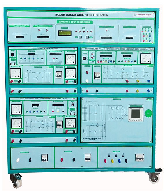
2.5KW GRID-TIED INVERTER:
- DC-DC BOOST CONVERTER———–1 No
- DC-DC Bi-Directional Buck-Boost Converter——–1 No
- 10KVA IGBT Based 3PH VOLTAGE SOURCE INVERTER-1 No
- FPGA SPARTAN6 BASED CONTROLLER—–1 No
- GRID-SIDE INTERFACE STUFF
DC-Dc Buck or Boost Converter
- 2Nos of Switching device SEMIKRON IGBT Rating @1200v,100A,20khz with proper heatsink and snubber circuit Used to form power circuit.
- Input voltage range
- Minimum: 300v Dc
- Output voltage range
- Maximum: 600V Dc
- Output power : 3000W(max)
- Switching Frequency—5-20khz
- 2 Nos of HCPL316J IC-based PWM driver circuit used
- One Hall effect current sensor used to sense the Input current
- One Hall effect current sensor is used to sense Inductor current and overload trip purpose.
- One hall effect voltage sensor is used to sense the I/P voltage.
- One hall effect voltage sensor is used to sense the o/p voltage.
- Voltage and current sensor o/pts terminated in front panel bs2 connector.
- Overload fuse protection is available.
- Over temperature, protection will be provided One no of 4inch cooling fan used to dissipate switching device heat
3.10 KVA IGBT Based 3PH VOLTAGE SOURCE INVERTER:
- Input: 1 Phase /3 phase 50 Hz AC.
- Output: 400V/10A (MAX), AC/DC on each Leg of 3 phase Bridge
- 3Nos 1200V, 100A SEMIKRON IGBT MODULE Used to form Inverter Bridge.Each IGBT module consists of two IGBTs.
- Built-in Short circuit, over current & over Temperature Protection available.
- 1200V, 60A Converter Bridge for AC-DC power conversion
- 15v/2A SMPS power supply and converter used to generate 4nos of isolated +15v supply for gate driver section.
- 4 Nos of Hall Effect current sensors(LEM MAKE-LA25-P) to sense the DC Link current & 3 output Currents of the Inverter Bridge.
- 6 nos of HCPL316J ic-based negative turn-off driver circuit will be used.
- All the PWM signals are isolated using Optoisolator
- Protection circuit for over current with LED indication
- Optically Isolated Fault signal from the driver is given to the Embedded/DSP Controllers for protection.
- Independent Power supplies for all isolated circuits.
- 0-900V Voltmeter to Indicate the DC Link Voltage
- All current, PWMS and feedback are terminated at the Front panel
- FRC Connectors are provided to Interface with the Embedded/DSP controllers
- All the Input/output Lines are terminated at Banana sockets.
- One no of 4inch cooling fan used to dissipate switching device heat
- Soft-copy and hard-copy manuals will be provided.

DC-DC Bi-Directional Buck-Boost converter
- 2Nos of Switching device SEMIKRON IGBT Rating @1200v,100A,20khz with proper heatsink and snubber circuit Used to form power circuit.
- Input voltage range
- Minimum: 300v Dc
- Output voltage range
- Maximum: 600V Dc
- Output power : 3000W(max)
- Switching Frequency—5-20khz
- 2 Nos of HCPL316J IC-based PWM driver circuit used
- One Hall effect current sensor used to sense the Input current
- One Hall effect current sensor is used to sense Inductor current and overload trip purpose.
- One hall effect voltage sensor is used to sense the I/P voltage.
- One hall effect voltage sensor is used to sense the o/p voltage.
- Voltage and current sensor points terminated in the front panel bs2 connector.
- Overload fuse protection is available.
- Over temperature, protection will be provided One no of 4inch cooling fan used to dissipate switching device heat
GRID-SIDE INTERFACE STUFF
- LA25-P HALLEFFECT Current sensors with signal conditioner – 3 nos(25Amps Current sensor), which is used to measure the grid side current.
- Three nos of hall effect voltage sensors(LV20-P) with signal conditioners are used to sense the grid voltage.
- 3Nos of Inductor Used to filter the grid side injected current.
- 3ph OP-AMP-based ZCD circuit used to generate synchronized PWM signals.
For More details contact: 7667134364
About Us
JSK LAB INSTRUMENTS was established in 2017, with a prime motto to design and develop Hardware and software solutions.
Quick Links
Our Products
Contact Us
Plot No. 16 ‘B’, Tropical Colony,
Thangaraji Street, Pallikaranai,
Chennai – 600100.
+91 76671 34364
+91 97915 60016
+91 96290 40634
sales.jsklab@gmail.com
jsklab783@gmail.com

