WIND TURBINE EMULATOR USING -PMSG
Product Specification:
Inverters: VSI/VIENNA/NPC/H-BRIDGE types
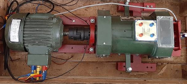
PMSG SETUP: 6KW DC Motor Coupled With 2.2KW PMSG
DC Motor Specifications:
- Power: 2KW
- Armature voltage: 220V DC
- Field voltage: 220V DC
- Speed: 1500 RPM
- Double-side shaft extension
PMSG (Generator):
- Type: Three-phase PMSG
- Power: 2KW
- Stator voltage: Three phase 230V AC,
- Speed: 1500 RPM
- DIRECT POWER CONTROL SCHEME FOR ACTIVE AND REACTIVE POWER
- All necessary test points are provided for external patching.
- All are included with the cabinet with a front panel sticker with the circuit diagram.
- A protection circuit is available to secure the module
- We also provide fault detection
- As per customer satisfaction, we provide the components in the product.
- We will make the inverter power rating aspire to the customer’s requirements.
For More details contact: 7667134364
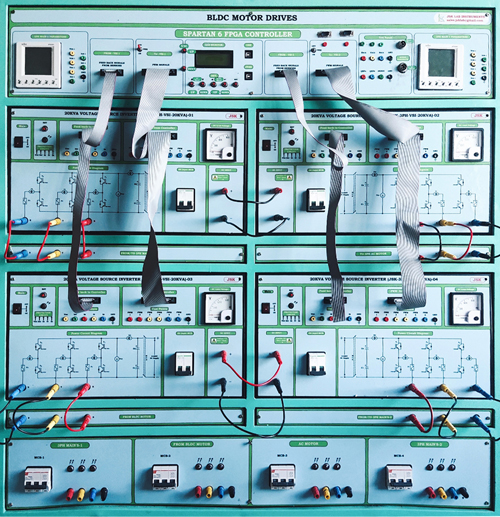
SPEED CONTROL OF BLDC MOTOR USING FPGA SPARTAN6 CONTROLLER
BLDC MOTOR
Brushless Permanent Magnet Motors, Permanent Magnet AC motors, Permanent Magnet Synchronous Motors etc. The confusion arises because a brushless DC motor does not directly operate a DC voltage source. However, as we shall see, the basic principle of operation is similar to a DC motor.
A Brushless DC motor has a rotor with permanent magnets and a stator with windings. It is essentially a DC motor turned inside out. The brushes and commutator have been eliminated and the windings are connected to the control electronics. The control electronics replace the function of the commutator and energize the proper winding. The energized stator winding leads the rotor magnet and switches just as the rotor aligns with the stator. There are no sparks, which is one advantage of the BLDC motor. The brushes of a DC motor have several limitations; brush life, brush residue, maximum speed, and electrical noise.
BLDC Motors are potentially cleaner, faster, more efficient, less noisy, and more reliable. However, BLDC motors require electronic control.
Brushless DC motors are used in a growing number of motor applications as they have many advantages:
- They have no brushes so they require little or no maintenance.
- They generate less acoustic and electrical noise than universal brushed DC motors.
- They can be used in hazardous operation environments (with flammable products).
- They also have a good weight/size-to-power ratio.
- Such motors have little rotor inertia. The coils are attached to the stator. The commutation is controlled by electronics. Commutation times are provided either by position sensors or by coils Back Electromotive Force measurements.
- In sensor mode, Brushless DC motors usually consist of three main parts: a Stator, a Rotor, and Hall Sensors.
STATOR
A basic three-phase BLDC motor Stator has three coils. In many motors, the number of coils is replicated to have a smaller torque ripple. Figure 1 shows the electrical schematic of the stator. It consists of three coils each including three elements in series, an inductance, a resistance, and one back electromotive force.
Figure 1. Stator Electrical Configuration (Three phases, three coils)
ROTOR
The rotor in a BLDC motor consists of an even number of permanent magnets. The number of magnetic poles in the rotor also affects the step size and torque ripple of the motor. More poles give smaller steps and less torque ripple. The permanent magnets go from 1 to 5 pairs of poles. In certain cases, it can go up to 8 pairs of poles.
Figure 2. Three phase three coil BLDC motor stator and rotor
BLDC OPERATION
A permanent Magnet AC motor, which has a trapezoidal back emf, is referred to as a brushless DC motor (BLDC). The BLDC drive system is based on the feedback of the rotor system at fixed points for the commutation of the phase currents.
Figure 3. Three-phase Inverter BLDC motor
The BLDC motor requires quasi-rectangle-shaped currents fed into the machine. Alternatively, the voltage may be applied to the motor every 120°, with a current limit to hold the current within motor capabilities. Because the phase currents are excited in synchronism with the constant part of the back emf, constant torque is generated.
The electromagnetic torque of the BLDC motor is related to the product of phase, back emf, and current. The back emf in each phase are trapezoidal in shape and are displaced by 120 electrical degrees with respect to each other in the 3-phase machine. A rectangle current pulse is injected into each phase so that the current coincides with the ackemf waveform; hence the motor develops an almost constant torque.
HALL SENSOR
Hall Effect sensor provides the portion of the information needed to synchronize the motor excitation with the rotor position in order to produce constant torque. It detects the change in magnetic field. The rotor magnets are used as triggers for the Hall Sensor. A signal conditioning circuit integrated within the Hall switch provides a TTL-compatible pulse with sharp edges. Three Hall Sensors placed 120° apart, are mounted on the stator frame. The Hall Sensor digital signals are used to sense the rotor position.
PHASE COMMUTATION
To simplify the explanation of how to operate a three-phase BLDC motor, a typical BLDC motor with only three coils is considered. As previously shown, phase commutation depends on the hall sensor values. When motor coils are correctly supplied, a magnetic field is created, and the rotor moves. The most elementary commutation driving method used for BLDC motors is an on/off scheme: a coil is either conducting or not conducting. Only two windings are supplied at the same time and the third winding is floating. Connecting the coils to the power and neutral bus induces the current flow. This is referred to as trapezoidal commutation or block commutation. To command brushless DC motors, a power stage made of 3 half bridges is used. Figure 4 below shows a 3-half bridge schematic.
SWITCHING COMMUTATION TABLE
CLOCKWISE ROTATION
| Hall Sensor Value (H3 H2 H1) | Phase | Switches |
| 101 | U-V | Q1;Q4 |
| 001 | U-W | Q1;Q6 |
| 011 | V-W | Q3;Q6 |
| 010 | V-U | Q3;Q2 |
| 110 | W-U | Q5;Q2 |
| 100 | W-V | Q5;Q4 |
MODULE DISCRIPTION
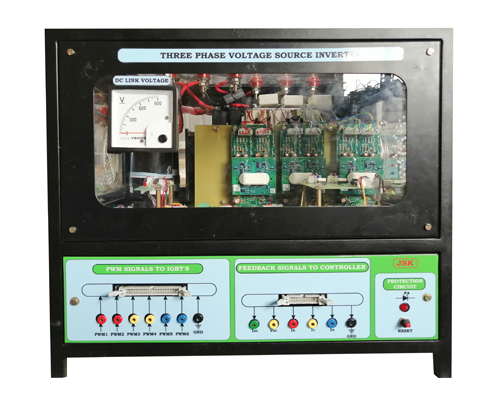
This module consists of
- Five Phase Three LevelInverter
- Three-phase bridge rectifier
- Six semi-cron IGBTs with drivers
- Over-voltage and current protection board
- DC link volt meter
- DC link capacitor -2200micro F
- Power ON/OFF switch
- MCB
- 12PWM test points, DC link voltage Vdc, current Idc, inverter AC output current Ir, Iy, Ib, and hall effect sensor feedback with respect to ground points.
- Speed feedback connecting point
- Input AC and output AC connecting points.
SPARATAN 6 FPGA CONTROLLER
- A separate detailed manual is provided for this controller.
BLDC MOTOR
- BLDC
- Voltage 230 VDC
- Current – 5A
- Rated Speed – 3000 rpm
- 1 hp


