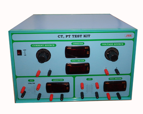
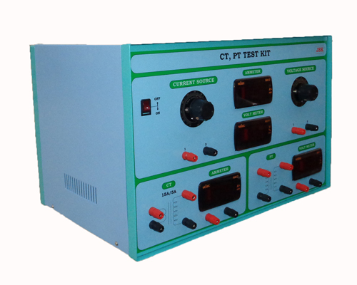
CT,PT CHARACTERISTICS TRAINER
Potential transformers are also known as voltage transformers and they are basically step-down transformers with extremely accurate turns ratio. Potential transformers step down the voltage of high magnitude to a lower voltage which can be measured with the standard measuring instrument. These transformers have a large number of primary turns and a smaller number of secondary turns.
A potential transformer is typically expressed in primary to secondary voltage ratio.
TRAINER KIT CONTAIN
- Digital panel meters (DPM)
- 230/9v potential transformer
- Single Phase Autotransformer
APPLICATION
- Application of sensing the voltages.
- Transmission lines
- Electronics applications.
- Small Solar Home Lighting System
Working
Potential transformer or voltage transformer gets used in electrical power systems for stepping down the system voltage to a safe value which can be fed to low ratings meters and relays. Commercially available relays and meters used for protection and metering, are designed for low voltage. This is the simplest form of potential transformer.
A voltage transformer or potential transformer is just like a theory of general-purpose step-down transformer. The primary of this transformer is connected across the phase and ground. Just like the transformer used for stepping-down purposes, the potential transformer i.e. PT has lower turns winding at its secondary. The system voltage is applied across the terminals of the primary winding of that transformer, and then proportionate secondary voltage appears across the secondary terminals of the PT. The secondary voltage of the PT is generally 10 V. In an ideal potential transformer or voltage transformer, when the rated burden gets connected across the secondary; the ratio of primary and secondary voltages of the transformer is equal to the turns ratio and furthermore, the two terminal voltages are in a precise phase opposite to each other. But in the actual transformer, there must be an error in the voltage ratio as well as in the phase angle between primary and secondary voltages. The errors in potential transformer or voltage transformer can be best explained by a phasor diagram, and this is the main part of potential transformer theory.


